Author name: globalsteelindustriesind@gmail.com

The Complete Guide to Piping Inspection Before Installation
Blogs

The Complete Guide to Piping Inspection Before Installation

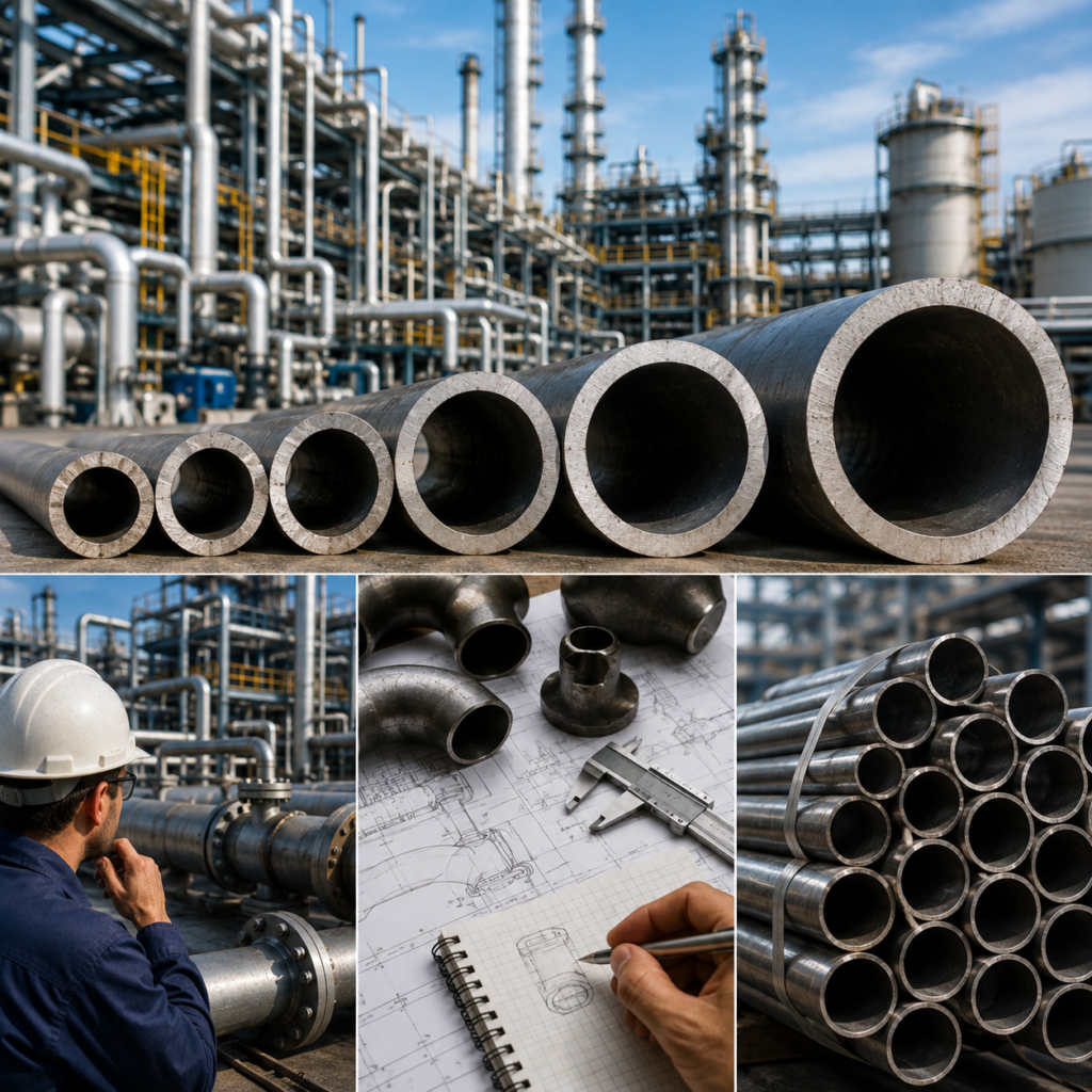
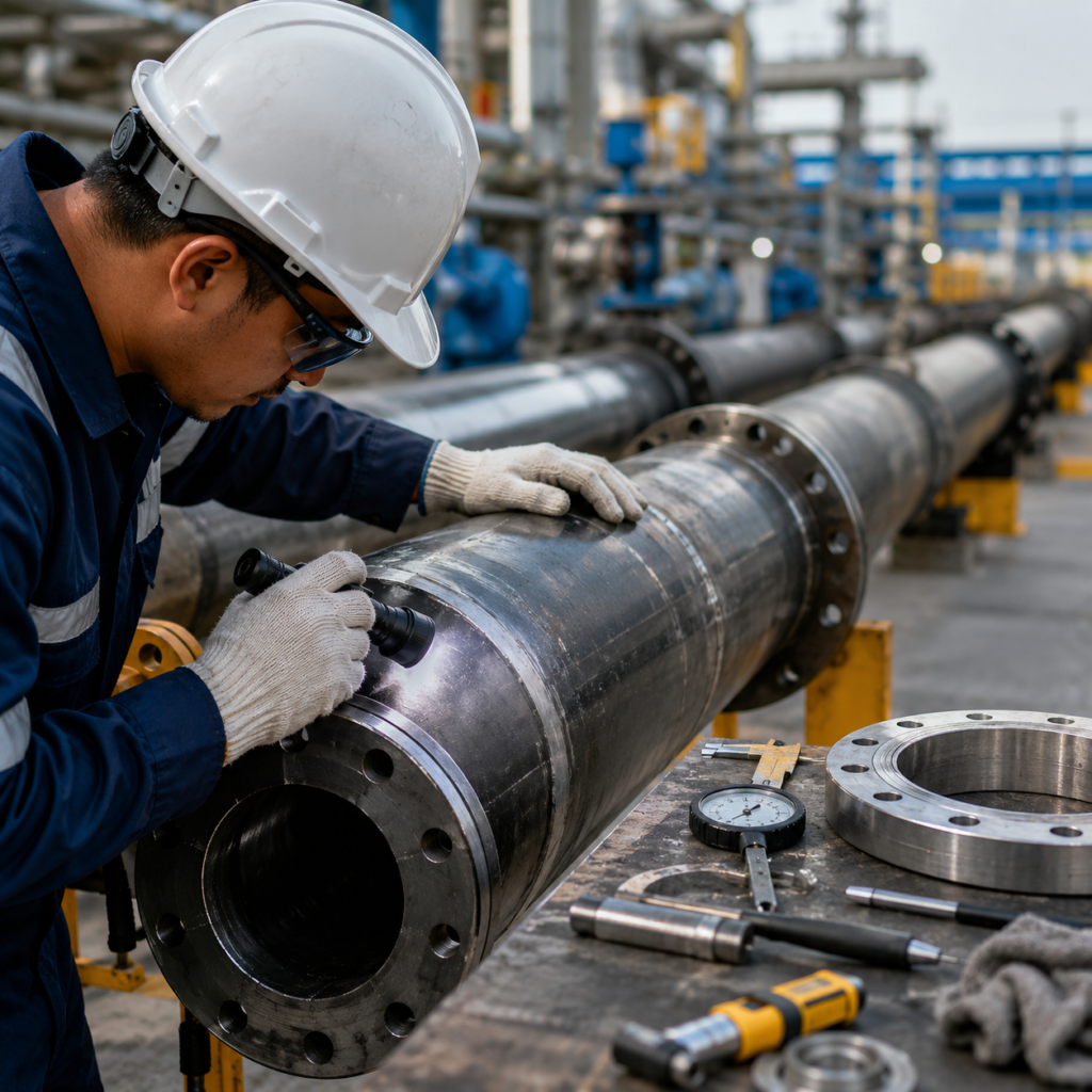
The Complete Guide to Piping Inspection Before Installation Industrial piping systems are essential to the safe and efficient operation of oil and gas facilities, petrochemical plants, power stations, water treatment facilities, manufacturing plants, and other industrial projects. Before any pipe, fitting, flange, valve, or related component is installed, it must undergo proper inspection to ensure that it meets project specifications and is suitable for its intended service. Piping inspection before installation is a critical quality-control process. It helps identify damaged, incorrect, non-compliant, or improperly documented materials before they become part of the piping system. Detecting problems at this stage can prevent costly rework, project delays, leaks, equipment failures, and potential safety risks. This guide explains the key steps involved in inspecting industrial piping materials before installation Why Is Pre-Installation Piping Inspection Important? Once piping materials are installed, identifying and correcting problems becomes more difficult and expensive. A damaged pipe, incorrect material grade, or mismatched fitting can affect the integrity of the entire system. Pre-installation inspection helps ensure that: Materials match the approved project specifications. Pipes and components are free from visible damage. Dimensions and wall thickness are within acceptable requirements. Material grades and markings are correctly identified. Supporting documents and certificates are available. Flanges, fittings, valves, and accessories are compatible with the piping system. Materials are properly stored and protected before installation. A systematic inspection process provides confidence that only suitable and verified materials move forward to fabrication and installation1. Verify Purchase Orders and Project Specifications The inspection process should begin by reviewing the relevant purchase documents and technical specifications. The inspector should compare the delivered materials with the approved requirements, including: Material grade Applicable standards Pipe size Wall thickness or schedule Length End preparation Pressure rating Manufacturing specification Required testing and inspection documents For example, a project requiring ASTM or ASME-compliant carbon steel piping should not receive a visually similar material manufactured to a different specification unless it has been properly approved. Document verification is the first step in preventing incorrect materials from entering the installation process 2. Check Material Identification and Markings A Mill Test Certificate, often referred to as an MTC or Material Test Certificate, provides documented information about the material supplied. Depending on the applicable standard and project requirements, an MTC may include: Manufacturer details Purchase order or product reference Material grade Heat number Chemical composition Mechanical properties Heat treatment details where applicable Test results Product dimensions Applicable standards The certificate allows the purchaser or inspection team to compare the actual material properties against the required specification. For example, if a project requires a particular ASTM or ASME material grade, the MTC can provide evidence that the supplied material meets the specified chemical and mechanical requirements. However, documentation alone is not sufficient if it cannot be correctly linked to the physical material. This is why marking and identification are equally important 3. Perform a Visual Inspection A detailed visual inspection should be carried out before installation. The objective is to identify visible defects, damage, or conditions that could affect the material’s performance. Inspectors should check for: Dents and deformation Cracks or surface defects Corrosion or rust Scratches and gouges Lamination or visible imperfections Damaged pipe ends Damaged threads Distorted flange faces Contamination Improper storage damage Pipes should also be checked for excessive ovality or bending that could create alignment problems during installation. For flanges, the raised face or sealing surface should be inspected carefully. Damage to the sealing surface may affect gasket performance and increase the risk of leakage. Any material showing significant damage should be clearly identified and prevented from being installed until it has been evaluated and approved for use4. Verify Dimensions and Wall Thickness Dimensional inspection is essential to ensure that piping materials will fit correctly within the system. Important measurements may include: Outside diameter Inside diameter Wall thickness Pipe length Flange dimensions Bolt-hole alignment Fitting dimensions End preparation Wall thickness is particularly important for pipes used in pressure applications. A pipe with insufficient wall thickness may not meet the design requirements for pressure, temperature, or mechanical loads. Measurements should be taken using calibrated inspection equipment such as vernier calipers, micrometers, ultrasonic thickness gauges, and other suitable instruments. The results should be compared with the applicable standards and project specifications5. Review Material Test Certificates and Documentation Material Test Certificates, commonly referred to as MTCs or Mill Test Certificates, provide important information about the materials supplied. Depending on the project requirements, an MTC may include: Material grade Heat number Chemical composition Mechanical properties Manufacturing specification Heat treatment information Test results The information on the certificate should match the identification markings on the physical material. Additional documentation may also be required, including: Inspection reports Hydrostatic test certificates Non-destructive testing reports Certificates of compliance Third-party inspection reports Documentation should be reviewed carefully before installation. Complete documentation without clear physical identification may create traceability issues, while correctly marked material without supporting certification may not meet project quality requirements. Both the material and its documentation must be properly connected.6. Inspect Pipes, Fittings, Flanges, and Valves SeparatelyDifferent piping components require different inspection considerations.PipesElbows, tees, reducers, and other fittings should be checked for correct size, schedule, material grade, end preparation, and visible defectsFlangesInspect flange faces for scratches, dents, corrosion, and other damage. Verify the flange type, pressure class, dimensions, facing, and bolt-hole arrangementValves Before installation, verify the valve type, size, pressure rating, material, end connection, and direction of flow where applicable. The valve should also be checked for visible damage and proper operation. A valve that is correct in size but has the wrong pressure rating or end connection can create significant installation problems 7. Check for Material Compatibility All components in a piping system must be compatible with the process conditions and with each other. The inspection team should confirm that the selected materials are suitable for factors such as: Operating pressure Operating temperature Fluid characteristics Corrosion conditions Mechanical loading Environmental exposure For example, using an incorrect gasket material with a particular chemical or temperature range may lead

The Importance of Traceability in Industrial Piping Materials
Blogs

The Importance of Traceability in Industrial Piping Materials

The Importance of Traceability in Industrial Piping Materials Industrial piping systems operate in demanding environments where safety, reliability, and compliance are essential. From oil and gas facilities and power plants to petrochemical units, water treatment systems, and offshore platforms, every pipe, fitting, flange, valve, and fastening component must meet specific technical and material requirements. In such applications, knowing what material was used, where it came from, how it was manufactured, and whether it meets the required standards is critical. This is where traceability in industrial piping materials plays a vital role. Traceability provides a documented connection between a physical product and its manufacturing, testing, inspection, and certification history. It helps project owners, EPC contractors, procurement teams, and quality inspectors verify that the materials installed in a piping system are exactly those specified for the project. What Is Material Traceability? Material traceability is the ability to track a product through the supply chain and connect it to relevant manufacturing and inspection records. For industrial piping materials, traceability may include information such as: Manufacturer name Material grade Product specification Heat number Batch or lot number Pipe size and wall thickness Pressure class Manufacturing standard Chemical composition Mechanical properties Test and inspection results Material Test Certificates Third-party inspection records This information allows project teams to verify the identity and quality of a material before it is installed. For example, a carbon steel pipe may be marked with a heat number. That heat number can be matched with the corresponding Mill Test Certificate to confirm the material’s chemical composition, mechanical properties, and manufacturing details. Without proper identification and documentation, it can become difficult to confirm whether a component genuinely meets the project specification Why Traceability Is Important in Industrial Piping1. Ensures Material Compliance Industrial projects are designed according to specific engineering standards and material specifications. A project may require materials manufactured to ASTM, ASME, API, EN, or other internationally recognized standards. Without proper traceability, it can be difficult to verify whether a supplied pipe or fitting actually meets the required specification. Traceability allows procurement and quality teams to compare the physical material with its documentation. This helps confirm critical details such as material grade, size, wall thickness, pressure rating, and testing requirements. For example, two piping components may look identical but have significantly different mechanical properties or corrosion resistance. Installing the wrong material can affect the safety and service life of the entire system. 2. Improves Safety and Reliability Piping systems may transport high-pressure fluids, steam, chemicals, hydrocarbons, or other hazardous substances. Material failure in these systems can lead to leaks, production shutdowns, environmental damage, equipment loss, or serious safety incidents. Traceability reduces the risk of unidentified or non-compliant materials entering the supply chain. When every critical component can be traced to verified manufacturing and testing records, project teams have greater confidence in the integrity of the piping system. This is especially important for applications involving: Oil and gas processing Petrochemical plants Power generation Offshore facilities Refineries High-temperature services High-pressure pipelines A documented traceability system supports better quality control before materials are installed and throughout the operational life of the facility 3. Supports Quality Control and Inspection Traceability is an important part of quality assurance during material procurement and project execution. Before dispatch or installation, inspectors may verify material markings against purchase orders, approved technical specifications, packing lists, and Material Test Certificates. A clear traceability system makes this process faster and more reliable. For example, a pipe may carry markings showing its grade, size, schedule, manufacturing standard, and heat number. The inspector can compare this information with the corresponding MTC and other quality documents. This process helps identify potential issues such as: Incorrect material grades Missing or incomplete certificates Mixed materials Incorrect dimensions Unapproved substitutions Documentation mismatches Materials from unidentified sources By identifying these problems early, companies can prevent costly installation errors and project delays4. Helps Manage Complex Supply Chains Industrial piping projects often involve multiple manufacturers, stockists, suppliers, fabricators, and logistics providers. A single project may require thousands of components sourced from different locations. Without a structured traceability process, managing this volume of material can become difficult. Proper identification and documentation help maintain control as materials move through the supply chain. Traceability should ideally continue through receiving, storage, cutting, fabrication, welding, and installation. For instance, when a large pipe is cut into smaller sections, the original heat number can be lost if proper identification procedures are not followed. Re-marking or traceability transfer procedures help maintain the connection between the cut pieces and their original material documentation. This is particularly important in fabrication yards and large construction projects where multiple material grades may be stored and processed simultaneousl 5. Makes Problem Investigation Easier If a material-related issue occurs during fabrication, testing, or operation, traceability makes it easier to investigate the source of the problem. By identifying the relevant heat number or batch number, engineers and quality teams can review the associated manufacturing and testing records. They can determine whether other materials from the same batch are affected and take appropriate action. This allows companies to isolate potentially problematic materials instead of inspecting or replacing an entire inventory. Effective traceability can therefore reduce investigation time, minimize operational disruption, and support more targeted corrective actions 6. Supports Regulatory and Project Documentation Requirements Many industrial projects require extensive quality documentation as part of their procurement and inspection procedures. EPC contractors and project owners may specify requirements for MTCs, inspection reports, pressure test records, NDT reports, and certificates of compliance. Traceability provides the connection between these documents and the actual materials supplied. However, documentation alone is not enough. The physical product must also be identifiable and correctly linked to its supporting records. A Material Test Certificate has limited value if there is no reliable method of confirming which physical pipe, flange, fitting, or fastener it belongs to. For this reason, proper material marking, tagging, labeling, and document control are essential parts of an effective traceability system Best Practices for Maintaining Material TraceabilityCompanies handling industrial piping materials should

Blogs

Piping Supply Chain in the Middle East: Challenges and Solutions

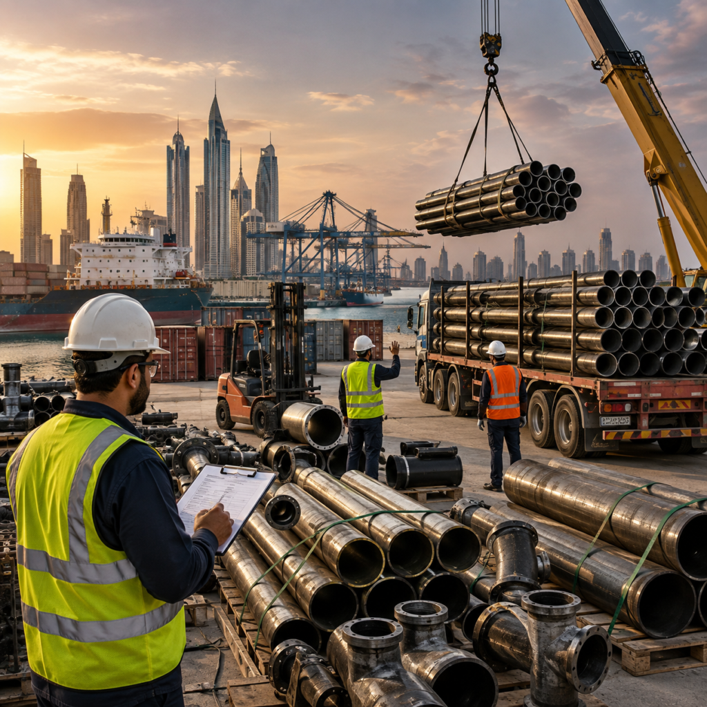
Piping Supply Chain in the Middle East: Challenges and Solutions The Middle East is home to some of the world’s largest oil and gas, petrochemical, power generation, water, desalination, and infrastructure projects. These industries depend on a continuous supply of pipes, fittings, flanges, valves, gaskets, fasteners, and other critical piping components. However, supplying piping materials across the region is not always straightforward. EPC contractors and project owners often face challenges related to long manufacturing lead times, fluctuating material availability, international logistics, technical compliance, inspection requirements, and the need for complete material traceability Supply-chain resilience has become an increasingly important priority in the UAE. In 2026, ADNOC launched an Industrial Resilience Program designed to strengthen supply chains, expand local manufacturing capacity, and improve business continuity for critical industrial products. For piping suppliers, the ability to provide the right material at the right time is no longer enough. Successful supply depends on technical knowledge, inventory planning, reliable sourcing networks, documentation control, and efficient logistics Challenge 1: Long Lead Times for Specialized Materials One of the most common challenges in the industrial piping supply chain is the availability of long-lead materials. Standard carbon steel pipes, fittings, and flanges may be readily available from regional stockholders. However, procurement becomes more complex when a project requires: Large-diameter pipes Heavy-wall or special schedules Alloy steel materials Duplex or super duplex stainless steel Sour-service materials Low-temperature grades Special coatings or linings Project-specific dimensions Client-approved manufacturers Specialized materials may require production at specific mills, additional testing, third-party inspection, or customer approval before shipment. This can significantly extend the procurement cycleSolution: Early Procurement and Demand Planning Long-lead items should be identified during the early stages of project planning. Procurement teams can create a critical-material register and prioritize components with the longest manufacturing or approval periods. Early engagement with approved suppliers and manufacturers can also help confirm production capacity and realistic delivery schedules. For major projects, framework agreements and long-term supplier relationships can provide greater visibility and reduce the risk of last-minute material shortages Challenge 2: Dependence on International Manufacturing The Middle East imports a significant volume of industrial piping materials from manufacturing centers across Asia, Europe, and other regions. International sourcing provides access to a wide range of products and material grades, but it can also introduce risks related to shipping delays, port congestion, geopolitical disruptions, changing freight costs, and customs procedures. Recent regional shipping disruptions have demonstrated how changes to major maritime routes can increase transit times and logistics costs Solution: Build a Diversified Supplier Network Relying on a single manufacturer or country of origin can create unnecessary supply risk. Piping suppliers and EPC contractors can improve resilience by developing approved alternative sources for critical materials. This may include manufacturers in different regions as well as local and regional stockholders. A diversified sourcing strategy should not compromise technical quality. Every alternative source must still meet the required standards, specifications, inspection requirements, and documentation requirements Challenge 3: Material Traceability and Documentation Both offshore and onshore facilities can operate under demanding pressure and temperature conditions. Offshore production systems may transport high-pressure oil and gas from wells to processing equipment. Piping materials must be capable of withstanding internal pressure, temperature fluctuations, vibration, and mechanical loads. Onshore facilities may include refineries, gas-processing plants, storage terminals, power stations, and pipeline networks. These systems can involve everything from low-pressure utility lines to high-pressure, high-temperature process piping. The correct pipe material and wall thickness should be selected using the applicable design code and engineering calculations. Factors may include: Design pressure Design temperature Material allowable stress Pipe diameter Corrosion allowance Manufacturing tolerances External loads Thermal expansion Cyclic service conditions Solution: Strong Documentation Control Suppliers should maintain an organized material-documentation system that links each product to its relevant certificates and identification records. Digital document management can improve traceability and reduce the risk of lost or mismatched certificates.Materials should also be checked before dispatch to confirm that markings, heat numbers, quantities, dimensions, and documentation correspond with the purchase order and project specification Challenge 4: Managing Inventory Without Excessive Stockholding Maintaining large inventories can improve delivery speed, but it also increases warehousing costs and ties up working capital. At the same time, keeping insufficient stock can result in emergency procurement and project delays. This is a particularly important challenge for suppliers handling a broad range of pipes, fittings, flanges, valves, gaskets, and fasteners across multiple material grades and standards Solution: Strategic Stocking Rather than stocking every possible product, suppliers can identify high-demand and business-critical items based on historical sales, regional project activity, customer requirements, and manufacturing lead times. Critical items with long replacement lead times may justify higher inventory levels, while commonly available materials can be replenished more frequently. The UAE’s industrial strategy increasingly supports this type of resilience through local manufacturing and stronger domestic supply capabilities. ADNOC’s 2026 Industrial Resilience Program includes initiatives focused on local production, demand visibility, and business continuity for strategic industrial products Challenge 5: Complex Logistics Across Multiple Countries The Middle East covers a large geographic area, and industrial projects may require materials to be delivered across the UAE, Saudi Arabia, Oman, Qatar, Kuwait, Bahrain, and other markets. Transporting piping materials involves several practical challenges, including: Oversized and heavy cargo Port and customs procedures Cross-border documentation Remote project locations Specialized lifting and handling Storage and preservation requirements Coordinating partial shipments Large pipes, heavy flanges, and bulk quantities of valves or fittings may require specialized logistics planningSolution: Regional Warehousing and Logistics Partnerships Regional warehousing can reduce delivery times by positioning critical inventory closer to major industrial markets. The UAE’s established ports, free zones, and logistics infrastructure support its role as a regional distribution hub. Energy logistics networks also depend on integrated warehousing, material handling, terminal operations, and offshore supply capabilities. Working with experienced freight forwarders and logistics providers can help suppliers coordinate transportation, customs clearance, cargo handling, and delivery schedulinChallenge 6: Meeting Project-Specific Technical Requirements Different oil and gas operators, EPC contractors, and industrial projects may have their own approved vendor lists, material specifications,

Offshore vs. Onshore Piping Different Demands, Different Materials
Blogs

Offshore vs. Onshore Piping: Different Demands, Different Materials

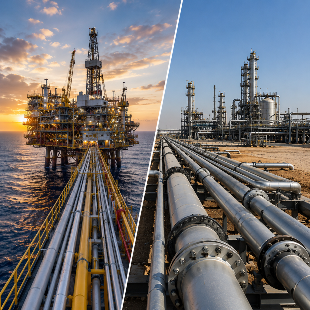
Offshore vs. Onshore Piping: Different Demands, Different Materials- Piping systems are essential to oil and gas, petrochemical, marine, power, and industrial infrastructure. However, the conditions experienced by an offshore piping system can be very different from those faced by an onshore facility. While both environments may handle hydrocarbons, gases, chemicals, water, and other process fluids, offshore installations are exposed to additional challenges such as saltwater, high humidity, restricted maintenance access, weight limitations, and continuous marine exposure. Onshore facilities, on the other hand, may involve large processing plants, long-distance pipelines, high ambient temperatures, desert conditions, and easier access for inspection and maintenance. These differences directly influence the selection of piping materials, coatings, wall thicknesses, joining methods, and corrosion-protection systems Environmental Challenges in Offshore Piping Offshore piping operates in one of the most demanding industrial environments. Exposure to seawater and salt-laden air creates a high risk of external corrosion. Key offshore challenges include: Continuous exposure to humidity Saltwater and chloride contamination Marine atmospheric corrosion Wave and weather exposure Limited maintenance access Space and weight restrictions Vibration and movement Corrosive process fluids High-pressure and high-temperature services Because maintenance and replacement can be more complex and expensive offshore, material reliability and long-term corrosion resistance are major priorities. A piping material that may perform adequately in a protected onshore environment may require additional protection or an alternative material for offshore service What Is a Welded Carbon Steel Pipe? Offshore piping operates in one of the most demanding industrial environments. Exposure to seawater and salt-laden air creates a high risk of external corrosion. Key offshore challenges include: Continuous exposure to humidity Saltwater and chloride contamination Marine atmospheric corrosion Wave and weather exposure Limited maintenance access Space and weight restrictions Vibration and movement Corrosive process fluids High-pressure and high-temperature services Because maintenance and replacement can be more complex and expensive offshore, material reliability and long-term corrosion resistance are major priorities. A piping material that may perform adequately in a protected onshore environment may require additional protection or an alternative material for offshore service Material Selection for Offshore Piping Carbon steel remains widely used in offshore applications because of its strength, availability, and cost efficiency. However, it usually requires an effective corrosion-management strategy when exposed to marine environments. Protective measures may include: External protective coatings Internal coatings or linings Corrosion allowance Cathodic protection where applicable Chemical treatment and corrosion inhibitors Regular inspection and maintenance For more corrosive environments, stainless steel, duplex stainless steel, super duplex, or other corrosion-resistant alloys may be selected. Duplex stainless steel is particularly valued in demanding applications because it can provide a combination of high strength and improved resistance to certain forms of corrosion. Material selection should always be based on the specific fluid, chloride exposure, temperature, pressure, and project requirements Corrosion: A Major Difference Between Offshore and Onshore Systems Corrosion management is important in every piping system, but offshore environments create additional risks. Saltwater contains chlorides that can contribute to localized corrosion and stress corrosion cracking in susceptible materials. Marine atmospheres can also accelerate the deterioration of unprotected carbon steel. Offshore piping systems may therefore require more extensive corrosion protection than comparable onshore systems. Onshore facilities can also experience serious corrosion, particularly when handling produced water, corrosive chemicals, hydrogen sulfide, carbon dioxide, or other aggressive fluids. However, the external environment may be easier to control compared with an offshore platform. The material selection process must therefore consider both internal corrosion from the process fluid and external corrosion from the operating environment Pressure and Temperature Requirements Both offshore and onshore facilities can operate under demanding pressure and temperature conditions. Offshore production systems may transport high-pressure oil and gas from wells to processing equipment. Piping materials must be capable of withstanding internal pressure, temperature fluctuations, vibration, and mechanical loads. Onshore facilities may include refineries, gas-processing plants, storage terminals, power stations, and pipeline networks. These systems can involve everything from low-pressure utility lines to high-pressure, high-temperature process piping. The correct pipe material and wall thickness should be selected using the applicable design code and engineering calculations. Factors may include: Design pressure Design temperature Material allowable stress Pipe diameter Corrosion allowance Manufacturing tolerances External loads Thermal expansion Cyclic service conditions Weight and Space Limitations Offshore Weight is a particularly important consideration for offshore platforms and floating facilities. Every component added to an offshore structure contributes to the overall topside weight. Heavy piping systems can increase structural requirements and installation complexity. Engineers may therefore evaluate materials and pipe dimensions not only for strength and corrosion resistance but also for weight efficiency. At the same time, offshore piping layouts are often compact. Limited space can make installation, welding, inspection, and maintenance more challenging.Material choices that reduce future maintenance requirements can therefore provide significant long-term benefits, even when the initial material cost is higher Onshore Piping and Large-Scale Infrastructure Onshore facilities generally have fewer restrictions related to structural weight and space. This allows greater flexibility in pipe routing, support design, equipment access, and maintenance. Large onshore facilities may include extensive networks of: Process piping Utility piping Firewater systems Steam lines Cooling water systems Oil and gas pipelines Chemical transfer lines Storage and terminal piping Carbon steel is widely used because it provides a cost-effective solution for many of these applications. Where corrosion, temperature, or process conditions require additional protection, stainless steel, alloy steel, lined pipe, or other specialized materials may be selected Joining and Fabrication Considerations Fabrication requirements can also differ significantly between offshore and onshore projects. Offshore construction often requires extensive planning because installation and repair work may be affected by weather, access restrictions, safety requirements, and available equipment. Prefabrication and modular construction can help reduce offshore installation time. High-quality welding procedures, qualified welders, inspection, and non-destructive testing are particularly important for critical piping systems. Onshore facilities generally provide greater access for fabrication and maintenance. However, large-scale projects may involve extensive field welding and thousands of piping connections, requiring careful quality control and coordination. For both environments, welding procedures and inspection requirements should comply with applicable project specifications

Seamless vs. Welded Carbon Steel Pipes Key Differences for Industrial Use
Blogs

Seamless vs. Welded Carbon Steel Pipes: Key Differences for Industrial Use

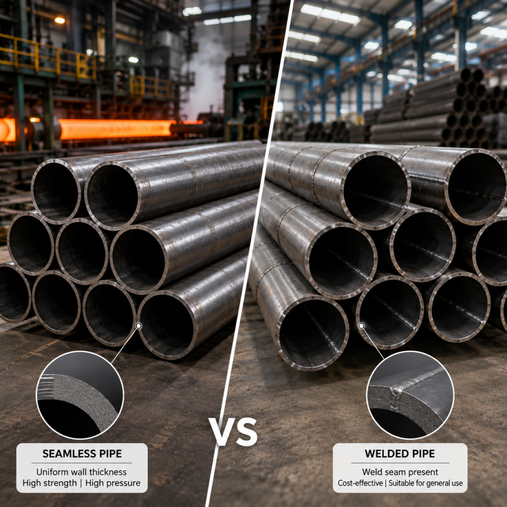
Seamless vs. Welded Carbon Steel Pipes: Key Differences for Industrial Use Carbon steel pipes are widely used across oil and gas, petrochemical, power generation, construction, water infrastructure, and general industrial applications. They provide a strong, economical, and versatile solution for transporting liquids, gases, steam, and other process media. When selecting carbon steel pipe, one of the most important decisions is whether to use seamless or welded pipe. Although both types can provide reliable service, their manufacturing methods, dimensional characteristics, pressure capabilities, availability, and cost can differ significantly. Understanding these differences helps engineers, contractors, procurement teams, and project managers select the most appropriate pipe for a specific application What Is a Seamless Carbon Steel Pipe? A seamless carbon steel pipe is manufactured without a longitudinal welded seam. The production process generally begins with a solid round steel billet, which is heated and pierced to create a hollow tube. The tube is subsequently rolled, sized, and finished to achieve the required dimensions and properties. Because there is no welded joint, seamless pipe provides a continuous material structure around the circumference. This characteristic makes seamless pipe particularly attractive for applications involving high pressure, elevated temperature, mechanical stress, or demanding operating conditions. Seamless carbon steel pipes are commonly specified for applications such as high-pressure process lines, boilers, heat exchangers, oil and gas systems, hydraulic services, and other critical industrial installations. What Is a Welded Carbon Steel Pipe? Welded carbon steel pipe is manufactured by forming a steel plate, strip, or coil into a cylindrical shape and joining the edges through a welding process. Depending on the manufacturing method, welded pipes can include ERW (Electric Resistance Welded), LSAW (Longitudinal Submerged Arc Welded), and SSAW (Spiral Submerged Arc Welded) pipes. ERW pipes are commonly manufactured from steel strip or coil and are widely used for utility, structural, water, and industrial applications. LSAW pipes are produced by forming steel plate and welding the longitudinal seam. They are particularly useful for large-diameter applications where strength, dimensional control, and wall thickness are important. SSAW pipes are manufactured by forming steel strip into a spiral configuration and welding the helical seam. They are frequently used in large-diameter water transmission, piling, and selected oil and gas applications Manufacturing DifferenceThe fundamental difference between seamless and welded pipes is the manufacturing processSeamless pipe Starts from a solid billet Billet is heated and pierced Hollow section is rolled and sized No longitudinal weld seam is present Welded pipe: Starts from steel plate, strip, or coil Material is formed into a cylindrical shape Edges are joined using a welding process Weld seam is inspected and controlled according to applicable standards Modern welding and inspection technologies have significantly improved the quality and reliability of welded pipes. Therefore, the presence of a weld does not automatically mean that a welded pipe is unsuitable for demanding industrial applications.Strength and Pressure Performance Seamless pipe is often preferred for particularly demanding pressure applications because it does not contain a longitudinal weld seam. The continuous construction can provide advantages in applications involving high pressure, high temperature, cyclic loading, or severe mechanical conditions. However, the actual pressure capability of a pipe depends on much more than whether it is seamless or welded. Pipe material grade, wall thickness, diameter, manufacturing standard, allowable stress, weld quality, design temperature, and applicable piping code all influence the final design. High-quality welded pipes manufactured to appropriate standards can provide excellent performance in pressure and process applications. Therefore, engineers should avoid assuming that every seamless pipe automatically has a higher pressure rating than every welded pipe. The complete specification must be evaluated Dimensional and Size Availability One significant advantage of welded pipe is its broad availability in large diameters and different wall thicknesses. Large-diameter seamless pipes can become more difficult and expensive to manufacture as size and wall thickness increase. Welded manufacturing processes can provide greater flexibility for producing large-diameter pipes from steel plate or coil. This makes LSAW and SSAW pipes particularly useful for large-diameter pipelines, water transmission systems, structural applications, and other projects requiring substantial pipe sizes. Seamless pipe, meanwhile, is widely available in many smaller and medium diameters and is frequently selected for high-pressure industrial services Cost Comparison Cost is another important difference between seamless and welded carbon steel pipes. Seamless pipe generally involves more intensive manufacturing processes, which can make it more expensive than comparable welded pipe. The price difference can become significant for large quantities or large-diameter requirements. Welded pipe can offer a cost-effective solution when the application does not require the specific characteristics associated with seamless construction. For large infrastructure projects, water pipelines, structural systems, and many general industrial services, welded carbon steel pipe can provide an attractive balance between performance and project cost. For critical high-pressure applications, the additional cost of seamless pipe may be justified by the service requirements Applications of Seamless Carbon Steel Pipes Seamless carbon steel pipes are commonly used where demanding operating conditions require reliable pressure containment and mechanical performance. Typical applications include: Oil and gas processing High-pressure piping Boiler and steam systems Power generation Hydraulic systems Petrochemical processing Heat exchanger systems High-temperature services Critical process piping The appropriate grade and schedule should always be selected according to the project’s design requirements and applicable standards Applications of Welded Carbon Steel Pipes Welded carbon steel pipes are used across a wide range of industrial and infrastructure projects. Common applications include: Water transmission Fire protection systems Utility piping Structural applications Oil and gas pipelines Low- and medium-pressure process systems Large-diameter transmission lines Piling and construction Industrial fabrication ERW, LSAW, and SSAW pipes each serve different requirements, so the manufacturing process should be selected according to diameter, wall thickness, pressure, application, and project specification Seamless vs. Welded Pipe: Key Comparison Factor Seamless Carbon Steel Pipe Welded Carbon Steel Pipe Manufacturing Produced from solid billet Produced from plate, strip, or coil Weld Seam No longitudinal weld Weld seam present Typical Cost Generally higher Generally more economical Large Diameters More limited or economically challenging Widely available High-Pressure Service Commonly selected Suitable

Understanding Pressure-Temperature Ratings for Industrial Valves
Blogs

Understanding Pressure-Temperature Ratings for Industrial Valves

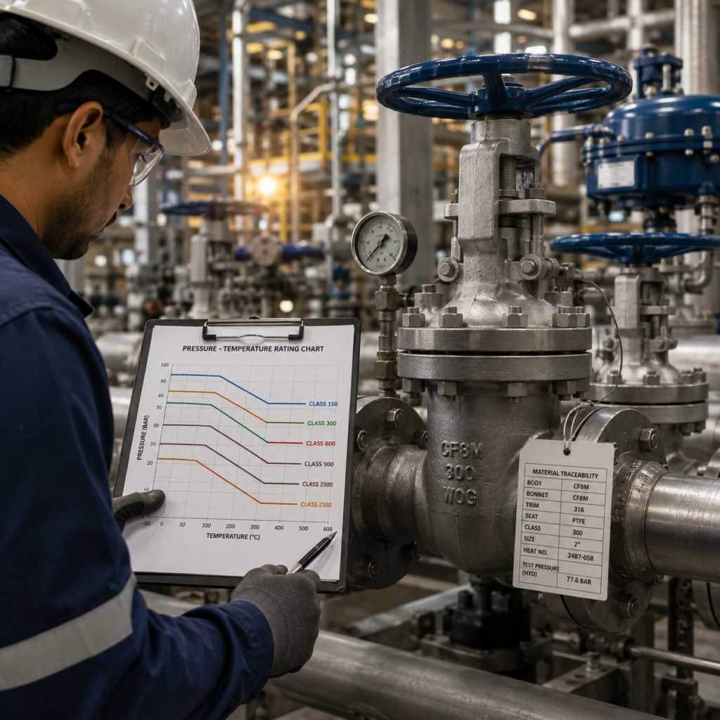
Understanding Pressure-Temperature Ratings for Industrial Valves Industrial valves are essential components in piping systems, controlling the flow, pressure, and direction of liquids, gases, steam, and other process media. However, selecting a valve based only on its nominal pressure rating can lead to serious design and operational problems. A valve’s ability to withstand pressure changes with temperature. As the operating temperature increases, the allowable pressure rating of many valve materials decreases. For this reason, engineers must evaluate pressure and temperature together when selecting valves for industrial applications. Understanding pressure-temperature ratings helps ensure that valves are suitable for the intended operating conditions and can provide safe, reliable, and long-term performance What Is a Pressure-Temperature Rating? A pressure-temperature rating defines the maximum allowable working pressure of a valve or pressure-containing component at a specific temperature. For example, a valve may be capable of handling a certain pressure at ambient temperature but have a lower allowable pressure when operating at an elevated temperature. This relationship exists because the mechanical properties of materials can change as temperature increases. Many metals experience a reduction in allowable strength at elevated temperatures, which affects the pressure they can safely contain. Therefore, a valve should never be selected based solely on its pressure class without checking the applicable temperature rating for its material Understanding Valve Pressure Classes Industrial valves are commonly supplied in pressure classes or ratings based on applicable standards. Common ASME pressure classes include: Class 150 Class 300 Class 600 Class 900 Class 1500 Class 2500 A higher pressure class generally indicates that the valve is designed for higher pressure-temperature service conditions. However, the pressure class is not a direct pressure value. For example, a Class 150 valve does not simply mean that the valve is rated for 150 psi under all operating conditions. The actual allowable pressure depends on factors including valve body material and operating temperature. The pressure-temperature tables in applicable standards are used to determine the maximum allowable pressure for a particular material group at a specific temperatureHow Temperature Affects Valve Pressure Ratings Temperature is one of the most important factors in valve selection. At elevated temperatures, the strength of many valve body materials decreases. As a result, the maximum pressure that the valve can safely withstand may also decrease. At very low temperatures, materials may also experience changes in toughness and ductility. Some materials can become more susceptible to brittle fracture under low-temperature conditions. This means that both high- and low-temperature applications require careful consideration of valve material and pressure-temperature limitations. Typical applications where temperature has a major impact include: High-temperature steam systems Refineries Petrochemical plants Power generation facilities LNG and cryogenic applications Chemical processing plants The actual pressure-temperature rating should always be verified against the applicable standard and the manufacturer’s product documentationThe Role of Valve Body Material The material used to manufacture the valve body has a major influence on its pressure-temperature rating. Common valve body materials include: Carbon steel Cast carbon steel Forged carbon steel Stainless steel Alloy steel Duplex stainless steel Special corrosion-resistant alloys Each material has different mechanical properties and temperature limitations. For example, carbon steel valves may be suitable for many general oil, gas, water, and industrial applications, while stainless steel may be preferred for applications requiring improved corrosion resistance. Alloy steel valves can be selected for elevated-temperature applications where additional mechanical strength is required. The correct material should therefore be selected based on the complete operating environment rather than pressure alone. ASME Standards and Pressure-Temperature Ratings Pressure-temperature ratings for flanged valves and fittings are commonly associated with standards such as ASME B16.34, while ASME flange standards such as ASME B16.5 provide pressure-temperature ratings for flanges and flanged fittings within their applicable scope. The applicable rating depends on factors such as: Pressure class Material group or grade Operating temperature Component design Applicable product standard Valve manufacturers may also provide additional pressure-temperature information for specific products and materials. Engineers should always use the applicable standard and manufacturer’s documentation for the exact valve being specified rather than relying on general assumptionsFactors That Affect Valve SelectionWhen selecting an industrial valve, the following factors should be evaluated together1. Design pressureThe maximum pressure the system may experience, including potential pressure surges where applicableThe Importance of Standards and Material Traceability Oil and gas projects require strict control over material specifications. Pipes, fittings, flanges, valves, and other pressure-containing components must be selected and supplied according to applicable project requirements and recognized standards. Depending on the application, specifications may reference organizations and standards such as: ASTM ASME API ISO NACE / AMPP ADNOC’s published engineering specifications include references to a broad range of these standards for piping materials, line pipe, corrosion-resistant materials, welding, valves, and related components Material traceability is particularly important for critical applications. Material test certificates, heat numbers, chemical composition, mechanical properties, inspection records, and other quality documentation may be required to verify that the supplied material matches the approved specification Supporting Major Oil and Gas Developments The continued development of the UAE’s offshore fields, gas-processing facilities, pipeline networks, LNG infrastructure, and downstream projects increases the importance of reliable piping materials. ADNOC’s operations span major offshore production assets, large onshore fields, gas-processing facilities, and extensive pipeline networks, demonstrating the scale and diversity of infrastructure that depends on properly engineered piping systems. Major developments also include projects designed around gas growth and lower-carbon operations, such as the Hail & Ghasha development and Ruwais LNG. These projects require piping solutions capable of meeting demanding process conditions while supporting long-term reliability and project-specific technical requirements Applications of Welded Carbon Steel PipesBefore selecting a piping material for an oil and gas application, engineers and procurement teams should evaluate1. Operating pressure and temperatureThe material and wall thickness must safely withstand design and operating conditions2. Fluid compositionHydrocarbons, water, gases, chemicals, CO₂, H₂S, and other components can affect material compatibility3. Corrosion riskInternal and external corrosion mechanisms must be evaluated over the expected service life4. Mechanical requirementsExternal loads, vibration, thermal expansion, and installation conditions can influence material selection5. Applicable standardsThe selected

The Role of Piping Materials in UAE Oil and Gas Infrastructure
Blogs

The Role of Piping Materials in UAE Oil and Gas Infrastructure

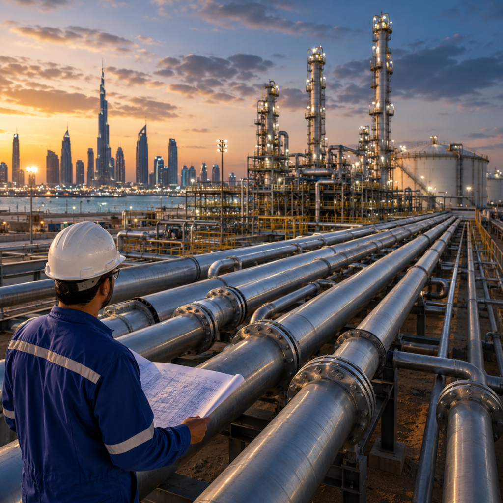
The Role of Piping Materials in UAE Oil and Gas Infrastructure The UAE’s oil and gas infrastructure operates across demanding environments that require reliable piping systems for upstream production, processing, refining, storage, transportation, and downstream operations. From offshore platforms and onshore processing facilities to refineries, terminals, and gas treatment plants, piping materials play a critical role in maintaining safe and efficient operations. Selecting the right pipe material is not simply a matter of choosing the strongest or most expensive option. Engineers must evaluate pressure, temperature, fluid composition, corrosion risk, mechanical loads, service life, and applicable project specifications. The wrong material can lead to premature corrosion, leakage, unplanned maintenance, and costly downtime. Carbon steel, stainless steel, alloy steel, and corrosion-resistant alloys each have an important role depending on the operating conditions and service requirements Carbon Steel: A Core Material for Industrial Piping Carbon steel remains one of the most widely used piping materials in oil and gas infrastructure. It offers a practical combination of mechanical strength, availability, weldability, and cost efficiency. Carbon steel pipes are commonly used for hydrocarbon transportation, utility systems, water services, structural applications, and many general process piping systems. Different grades and wall thicknesses can be selected according to pressure and temperature requirements. However, carbon steel is susceptible to corrosion when exposed to water, oxygen, carbon dioxide, hydrogen sulfide, and other aggressive environments. As a result, corrosion allowance, protective coatings, internal linings, chemical treatment, or alternative materials may be required depending on the service. For many applications, carbon steel provides an economical solution when the corrosion environment is properly controlled Stainless Steel for Corrosion Resistance Stainless steel piping is often selected where improved corrosion resistance is required. Its chromium content provides greater resistance to oxidation and corrosion than standard carbon steel, making it suitable for selected process, chemical, marine, and utility applications. Different stainless steel grades offer different levels of corrosion resistance and mechanical performance. Material selection must consider the actual process fluid and environmental conditions rather than relying only on the general classification of the material. In chloride-containing environments, for example, certain stainless steel grades may be more suitable than others. Temperature, concentration, pressure, and exposure conditions can all influence material performance. Stainless steel may have a higher initial cost than carbon steel, but its corrosion resistance can reduce maintenance requirements and improve long-term service life in suitable applications. Alloy Steel and High-Temperature Applications Alloy steel piping is used where operating temperatures and mechanical requirements exceed the capabilities of standard carbon steel grades. In refineries, power generation facilities, and high-temperature process systems, elevated temperatures can reduce material strength over time. Alloying elements such as chromium and molybdenum can improve high-temperature strength and resistance to certain forms of degradation. The appropriate alloy steel grade must be selected according to design temperature, pressure, creep considerations, welding requirements, and the applicable piping code. Proper material traceability and quality documentation are also important for critical piping systems, particularly where project specifications require material test certificates and controlled manufacturing standards Duplex and Corrosion-Resistant Materials For highly demanding offshore and corrosive services, duplex stainless steels and other corrosion-resistant alloys may be considered. These materials can provide a combination of strength and resistance to challenging environments. Offshore installations can expose piping systems to saltwater, humidity, chlorides, and corrosive process fluids. In addition, sour service conditions involving hydrogen sulfide may require materials selected specifically for the expected operating environment. Although these materials can have a higher initial procurement cost, they may offer advantages where conventional carbon steel would require extensive corrosion protection or frequent replacement. The selection should always be based on project-specific engineering requirements, material compatibility, and recognized industry standards Material Selection for Sour and Corrosive Service Material selection becomes especially important in sour service and other corrosive environments. Hydrogen sulfide, carbon dioxide, chlorides, moisture, and elevated temperatures can create conditions that increase the risk of corrosion and material degradation. In such applications, material selection may need to comply with standards covering resistance to sulfide stress cracking and other environmental damage mechanisms. ADNOC’s published engineering specifications reference standards including NACE MR0175 / ISO 15156 for materials used in H₂S-containing oil and gas production environments, highlighting the importance of matching piping materials to the expected service conditions. Depending on the application, engineers may consider carbon steel with corrosion allowance and protective measures, stainless steel, duplex stainless steel, or other corrosion-resistant alloys Offshore vs. Onshore Piping Requirements The UAE’s oil and gas infrastructure includes both extensive onshore facilities and major offshore operations. ADNOC Offshore operates across multiple fields, islands, super complexes, and offshore structures, creating demanding requirements for piping materials exposed to marine conditions. Offshore piping systems must account for: Saltwater and chloride exposure High humidity and marine atmosphere Corrosive process fluids Weight limitations Limited maintenance access Pressure and temperature variations Long-term reliability requirements Onshore facilities may face different challenges, including high ambient temperatures, desert conditions, large pipeline networks, processing operations, and demanding hydrocarbon services. Material selection must therefore be based on the specific operating environment rather than applying a single solution across every facility Pipeline Materials and UAE Energy Infrastructure Pipelines form a vital part of the UAE’s energy infrastructure. ADNOC Gas operates a gas pipeline network of more than 3,260 km, supplying customers across Abu Dhabi, Dubai, and the Northern Emirates and meeting approximately 60% of UAE gas requirements. Large pipeline systems require careful selection of: Pipe material grade Outside diameter Wall thickness Corrosion allowance Coating system Welding requirements Inspection and testing procedures Design pressure and temperature For transmission pipelines, carbon steel is commonly used because of its strength and economic advantages. However, external coatings, cathodic protection, and corrosion-management programs can play an important role in protecting long pipeline systems. In more corrosive process environments, internally clad, lined, or corrosion-resistant materials may be considered. ADNOC’s published piping material specifications also reference API standards covering conventional line pipe and corrosion-resistant alloy clad or lined steel pipe The Importance of Standards and Material Traceability Oil and gas projects require strict control over material specifications. Pipes,

How to Select the Right Pipe Schedule
Blogs

How to Select the Right Pipe Schedule for Your Application

How to Select the Right Pipe Schedule for Your Application Pipe schedule refers to the wall thickness of a pipe, and selecting the correct schedule is critical for ensuring structural integrity, pressure containment, and long-term reliability of piping systems. The correct wall thickness must withstand internal pressure, external loads, temperature variations, corrosion, erosion, and mechanical stresses throughout the intended service life. For industrial piping systems, selecting a pipe based only on nominal diameter is not sufficient. Engineers must also consider the pipe schedule, material grade, design pressure, operating temperature, corrosion allowance, joining method, and applicable piping code. This guide explains the pipe schedule system and the key factors that should be evaluated when selecting the appropriate wall thickness. Understanding the Pipe Schedule System Pipe schedules are standardized wall-thickness designations commonly specified under ASME B36.10M for welded and seamless carbon and alloy steel pipes and ASME B36.19M for stainless steel pipe. Common schedule designations include: SCH 5 and SCH 10 for relatively light-wall applications SCH 20 for selected low-pressure services SCH 40 for general-purpose industrial applications SCH 80 for higher-pressure and more demanding services SCH 120 and SCH 160 for heavy-wall applications STD, XS, and XXS for traditional standard, extra-strong, and double-extra-strong designations An important point is that a schedule number does not represent a fixed wall thickness. The actual wall thickness changes according to the nominal pipe size (NPS). For example, SCH 40 pipe will have different wall thicknesses at different pipe diameters. Therefore, specifications should identify the complete pipe size and schedule rather than referring only to the schedule number Pressure Rating and Wall Thickness Calculations Design pressure is one of the primary factors influencing pipe schedule selection. A pipe must have sufficient wall thickness to safely contain the internal pressure under the specified operating conditions. The required wall thickness is determined using the applicable engineering code and considers factors such as: Design pressure Design temperature Allowable material stress Outside diameter Weld quality and joint efficiency Corrosion or erosion allowance Manufacturing tolerances Mechanical and external loading Piping systems may be designed according to standards such as ASME B31.1 for power piping, ASME B31.3 for process piping, or other applicable codes depending on the service. After calculating the required minimum thickness, the engineer must account for manufacturing tolerances and any specified corrosion allowance before selecting a commercially available pipe schedule. A higher schedule generally provides a thicker wall and greater resistance to internal pressure, but it also increases pipe weight, material consumption, welding requirements, handling difficulty, and overall project cost. Corrosion Allowance and Service Life Corrosion is another important consideration when selecting pipe wall thickness. In services involving water, chemicals, hydrocarbons, steam, or corrosive process fluids, the internal pipe surface may gradually lose material during operation. Engineers may therefore specify a corrosion allowance in addition to the calculated pressure-retaining wall thickness. The required allowance depends on the expected corrosion rate, operating environment, design life, fluid characteristics, and corrosion-control measures. For highly corrosive services, simply increasing the pipe schedule may not always be the best solution. Material selection may also need to be changed. Stainless steel, duplex stainless steel, alloy steel, or other corrosion-resistant materials may provide better long-term performance depending on the application     Temperature Effects on Pipe Selection Operating temperature can significantly influence the allowable stress and mechanical properties of the pipe material. At elevated temperatures, some materials experience reduced strength, meaning a thicker wall may be required to withstand the design pressure. High-temperature systems such as steam, power generation, refining, and petrochemical processing therefore require careful evaluation of both pipe material and wall thickness. At low temperatures, engineers must consider material toughness and the potential for brittle fracture. The selected material grade may need to satisfy specific impact-testing requirements. Consequently, the correct pipe schedule cannot be selected independently from the pipe material and design temperature Schedule Selection for Different Applications Different industrial applications require different wall thicknessesSchedule 10Schedule 10 is often selected for applications where relatively light wall thickness is acceptable and pressure and mechanical requirements are moderate. It is also commonly encountered in certain stainless steel piping systemsSchedule 40 Schedule 40 is widely used for general industrial, commercial, utility, and process piping. It provides a practical balance between strength, weight, availability, and cost for many applications Schedule 80Schedule 80 provides a thicker wall and is frequently specified where higher pressure, greater mechanical protection, or increased resistance to wear is required. It is commonly found in chemical processing, industrial utilities, hydraulic applications, and demanding process systemsSchedule 160 Schedule 160 and XXS represent substantially heavier-wall options and are used for specialized high-pressure or high-stress applications where the engineering design requires increased wall thickness. However, these examples should not be treated as universal rules. The correct schedule must always be established from the project design conditions and applicable engineering standards Pipe Schedule and Fluid Flow Pipe schedule can also affect the internal diameter of a piping system. For a given NPS, increasing the schedule increases the wall thickness and reduces the internal diameter. This can affect flow velocity, pressure drop, pumping requirements, and overall system efficiency. For example, replacing a lighter-wall pipe with a significantly heavier-wall pipe without reviewing hydraulic calculations could reduce the available internal flow area. Therefore, pipe schedule selection should be coordinated with the project’s hydraulic design rather than evaluated solely from a pressure-containment perspective Impact of Schedule on Fittings and Flanges Pipe schedule must also be coordinated with fittings, flanges, valves, and other components. Butt-weld fittings should be compatible with the pipe wall thickness and welding preparation. In some cases, differences in wall thickness require appropriate transition or beveling details according to the applicable fabrication standard. Forged fittings such as socket-weld and threaded fittings are generally specified using pressure classes rather than pipe schedules. Their pressure-temperature rating must therefore be checked against the piping system’s design conditions. Flanges are also commonly selected according to pressure class, flange facing, material, size, and applicable standards. The connection between the flange and pipe must be properly engineered

Flanges and Gaskets Getting the Combination Right
Blogs

Flanges and Gaskets: Getting the Combination Right

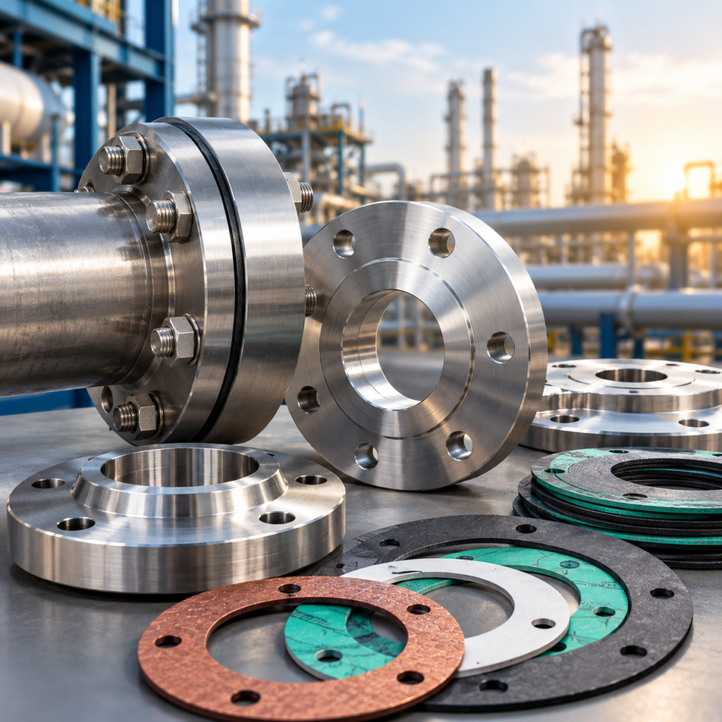
Flanges and Gaskets: Getting the Combination Right A flanged joint’s performance depends on the correct combination of flange face type, gasket material and type, bolt load, and installation procedure. Even high-quality flanges can leak if the wrong gasket is selected or if the gasket does not receive sufficient seating stress. For industries such as oil and gas, petrochemicals, power generation, water treatment, marine, and general process engineering, proper flange and gasket selection is essential for maintaining pressure integrity and preventing fluid leakage. Understanding how these components work together helps engineers, maintenance teams, and procurement professionals select reliable sealing solutions for their applications Matching Gasket Type to Flange Face Raised face flanges use spiral wound or ring gaskets sized to fit within the raised face area. Flat face flanges require full-face gaskets that extend to the bolt holes. Ring type joint flanges require metallic ring gaskets (oval or octagonal) that fit precisely in the machined groove. Using a gasket intended for one face type on an incompatible flange face will result in poor seating and leakage. Gasket Seating Stress and Bolt Load Raised face (RF) flanges are commonly used in industrial piping systems. Spiral wound gaskets, compressed fiber gaskets, and other suitable gasket types can be selected according to the pressure, temperature, and media. The gasket should be correctly sized so that it sits evenly on the sealing surface without interfering with the pipe bore Flat face (FF) flanges generally require full-face gaskets. These gaskets extend across the entire flange face and include bolt-hole openings. Using a gasket designed specifically for a flat-face connection helps distribute bolt load more evenly and reduces the risk of flange damage Ring type joint (RTJ) flanges use metallic ring gaskets installed into precision-machined grooves. Oval and octagonal RTJ rings are commonly used for demanding high-pressure and high-temperature applications. The gasket and groove dimensions must correspond precisely to ensure proper metal-to-metal sealingSelecting the correct gasket for the flange facing is therefore not simply a matter of matching dimensions. The gasket design, material, thickness, hardness, and sealing characteristics must also be appropriate for the service conditions Gasket Seating Stress and Bolt Load Bolt load is one of the most important factors influencing gasket performance. A gasket must be compressed sufficiently to conform to microscopic irregularities on the flange surfaces and create a continuous sealing barrier. Gasket design calculations consider factors such as gasket seating stress and the pressure that will be experienced during operation. ASME design methodologies, including those historically associated with Appendix 2 calculations, can be used for appropriate flange and bolting design If the applied bolt load is too low, the gasket may not seal properly. If the load is excessive, the gasket may be crushed or the flange may become distorted. For this reason, bolts should generally be tightened using a controlled procedure rather than simply tightening them as much as possible. A cross-pattern or star-pattern sequence is commonly used to distribute the load progressively across the flange. For critical applications, controlled torque tightening or tensioning equipment may be used to achieve more consistent bolt loading Temperature and Chemical Compatibility Gasket selection must also consider the fluid being handled and the operating environment. Graphite-based gaskets are widely used in applications involving elevated temperatures and many industrial fluids. Spiral wound gaskets with graphite filler are frequently selected for steam, hydrocarbons, and process services where their temperature resistance and compressibility are advantageous. PTFE gaskets are known for their strong chemical resistance and can be suitable for aggressive chemical services. However, their allowable operating temperature, pressure, and creep characteristics must be considered before selection. Metallic RTJ gaskets are particularly suitable for high-pressure and high-temperature services where conventional soft gaskets may not provide the required sealing performance. It is important not to select a gasket solely because it is rated for a particular temperature. Chemical compatibility, pressure, flange material, cycling conditions, gasket thickness, and installation requirements should all be evaluated.   Importance of Flange Surface Condition Even the correct gasket can fail when the flange sealing surface is damaged or contaminated. Scratches, corrosion, dents, warping, excessive surface roughness, or foreign particles can prevent the gasket from making uniform contact. Before installation, flange faces should therefore be inspected and cleaned. The required surface finish depends on the flange and gasket type. A surface that is too smooth may not provide sufficient mechanical engagement for certain gasket designs, while an excessively rough surface can make sealing difficult. Flanges should also be aligned correctly before bolts are tightened. Forcing misaligned flanges together with excessive bolt load can introduce unwanted stresses and create an uneven gasket load Common Causes of Flange Joint Failure Several installation and operating problems can contribute to flange leakage. Common causes include: Incorrect gasket type or dimensions Incompatible gasket material Insufficient bolt load Excessive or uneven bolt tightening Incorrect tightening sequence Damaged flange sealing surfaces Flange misalignment Reusing gaskets that are intended for single installation Pipe loads or vibration affecting the joint Thermal expansion and contraction Pressure and temperature cycling Corrosion of flange or bolting components Leakage can become particularly serious when the fluid is hazardous, flammable, corrosive, or maintained at high pressure. Preventive inspection and appropriate maintenance procedures are therefore important for critical piping systems Best Practices for Flange and Gasket Installation Reliable sealing begins before the gasket is installed. The flange faces should be cleaned and inspected, and the gasket should be checked for damage, contamination, or incorrect dimensions. The gasket should be positioned accurately without excessive stretching or distortion. Bolts should be inspected for suitable condition and compatibility with the flange assembly. During tightening, the recommended sequence and torque values should be followed. Multiple tightening passes can help achieve more uniform bolt loading. For critical systems, calibrated torque tools or hydraulic tensioning equipment may provide better control. After installation, the joint should be inspected according to the applicable project and safety procedures. In demanding services, periodic inspection can help identify corrosion, bolt loosening, gasket degradation, or other conditions that could eventually result in leakage

Blogs

Carbon Steel Pipes vs. Stainless Steel Pipes: Which Is Right for Your Project?

Carbon Steel Pipes vs. Stainless Steel Pipes: Which Is Right for Your Project? When selecting piping materials for industrial projects in the UAE and Middle East, one of the most critical decisions is choosing between carbon steel and stainless steel pipes. Both materials offer distinct advantages, and the right choice depends on your application, environment, and budget Understanding Carbon Steel Pipes Carbon steel pipes are widely used across oil and gas, construction, and petrochemical industries due to their exceptional strength and cost-effectiveness. Available in seamless and welded variants, carbon steel pipes handle high-pressure and high-temperature environments with ease. OIS Middle East stocks carbon steel pipes from ½” to 36″ in schedules ranging from 10 to XXS, meeting ASTM and API 5L standards Understanding Stainless Steel Pipes Stainless steel pipes offer superior corrosion resistance, making them ideal for applications involving chemicals, seawater, or food-grade processes. Grades like 304 and 316L provide excellent durability in corrosive environments commonly found across Gulf region industries. Key Differences: Strength, Corrosion, and Cost Carbon steel is stronger and more affordable but susceptible to rust without protective coatings. Stainless steel costs more upfront but delivers longer service life in corrosive settings. For most oil and gas pipelines in the UAE, carbon steel remains the industry standard due to pressure ratings and cost efficiency Making the Right Choice for Middle East Projects Projects in high-temperature environments such as refineries and power plants typically favour carbon steel. Offshore and marine applications benefit from stainless steel’s corrosion resistance. OIS Middle East supplies both materials with full mill test certificates and international compliance documentation Conclusion Whether your project demands carbon steel or stainless steel pipes, OIS Middle East provides certified, ready-stock solutions across Dubai, Abu Dhabi, and Ras Al Khaimah. Contact our technical team for guidance on the best material specification for your application. Read more

Scroll to Top